Introduction
In the input week, I designed a special board for this week to match the two experiments that I carried out, where I using the variable resistance with the LED, and using the Ultra Sensor,
group assignment: you can chack here
probe an input device's analog levels and digital signalsExperience
In computing, an input device is a piece of computer hardware equipment used to provide data and control signals to an information processing system such as a computer or information appliance. Examples of input devices include keyboards, mouse, scanners, digital cameras, joysticks, and microphones.
I started designing a special board for this week
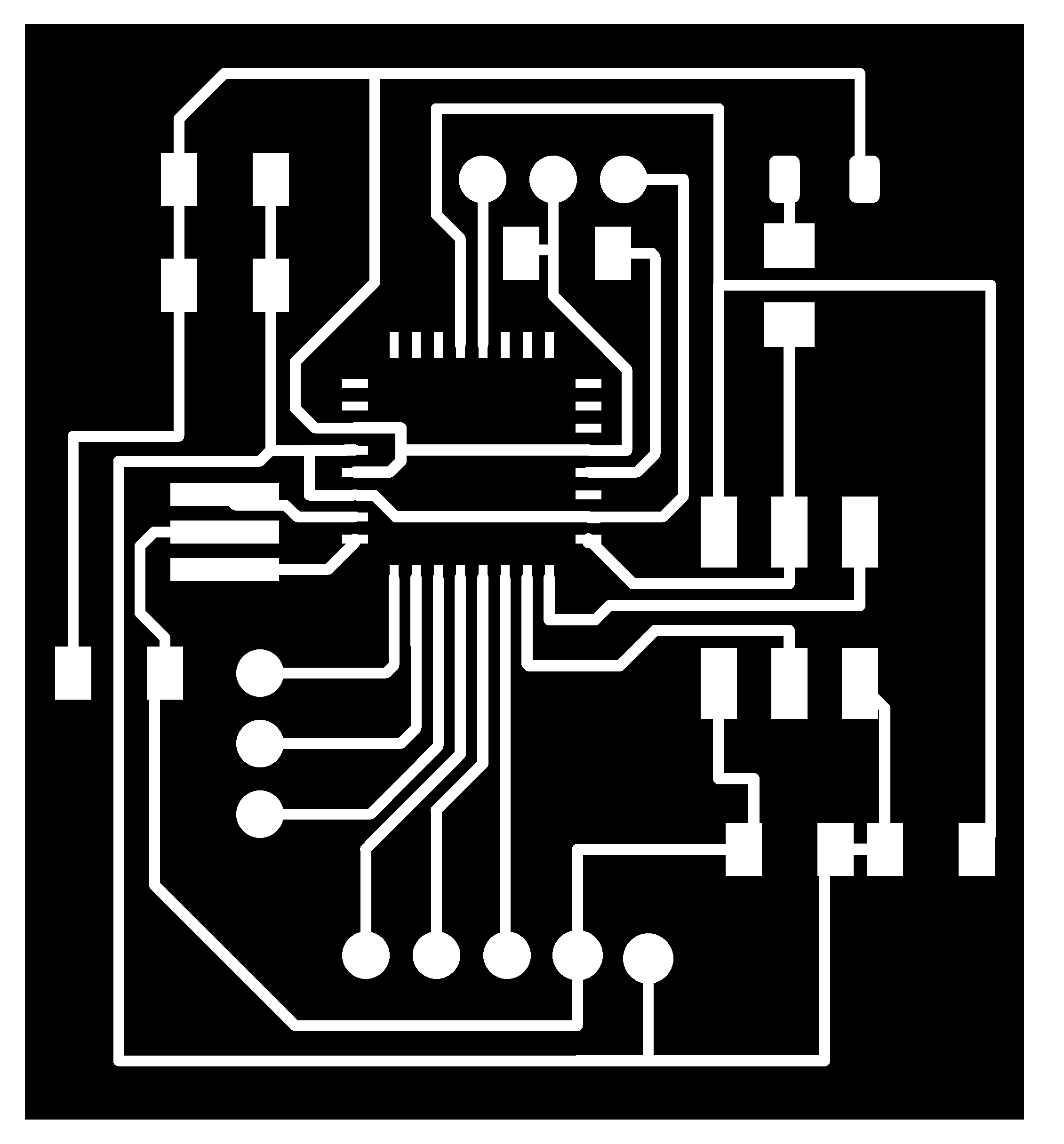
I used an atmega328p at design a board this week by eagle software It started with the additions of atmega328p, then the additions of input and output
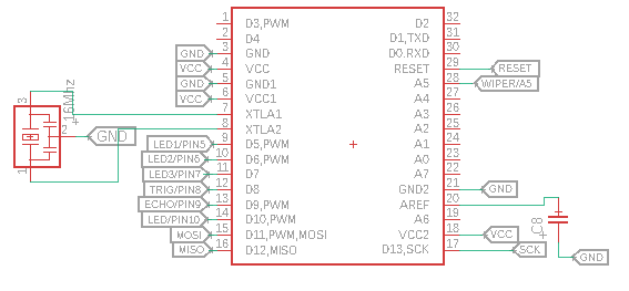
Then I added an ISP to enable the board programming

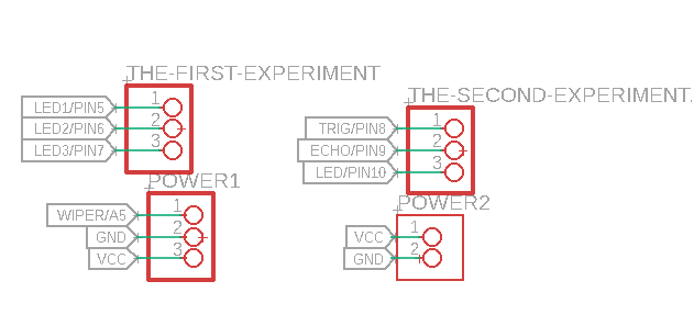
Then I added the input and output pins that I needed in the two experiments as shown in the picture below. In the first experiment, I added 3 LEDs in addition to the variable resistance and in the second experiment, I used an ultrasonic sensor with an LED.
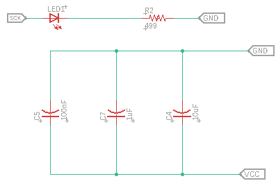
In addition to a LED, I added it to light up when the board is programmed, and I added three capacitors to maintain the stability of the circuit.
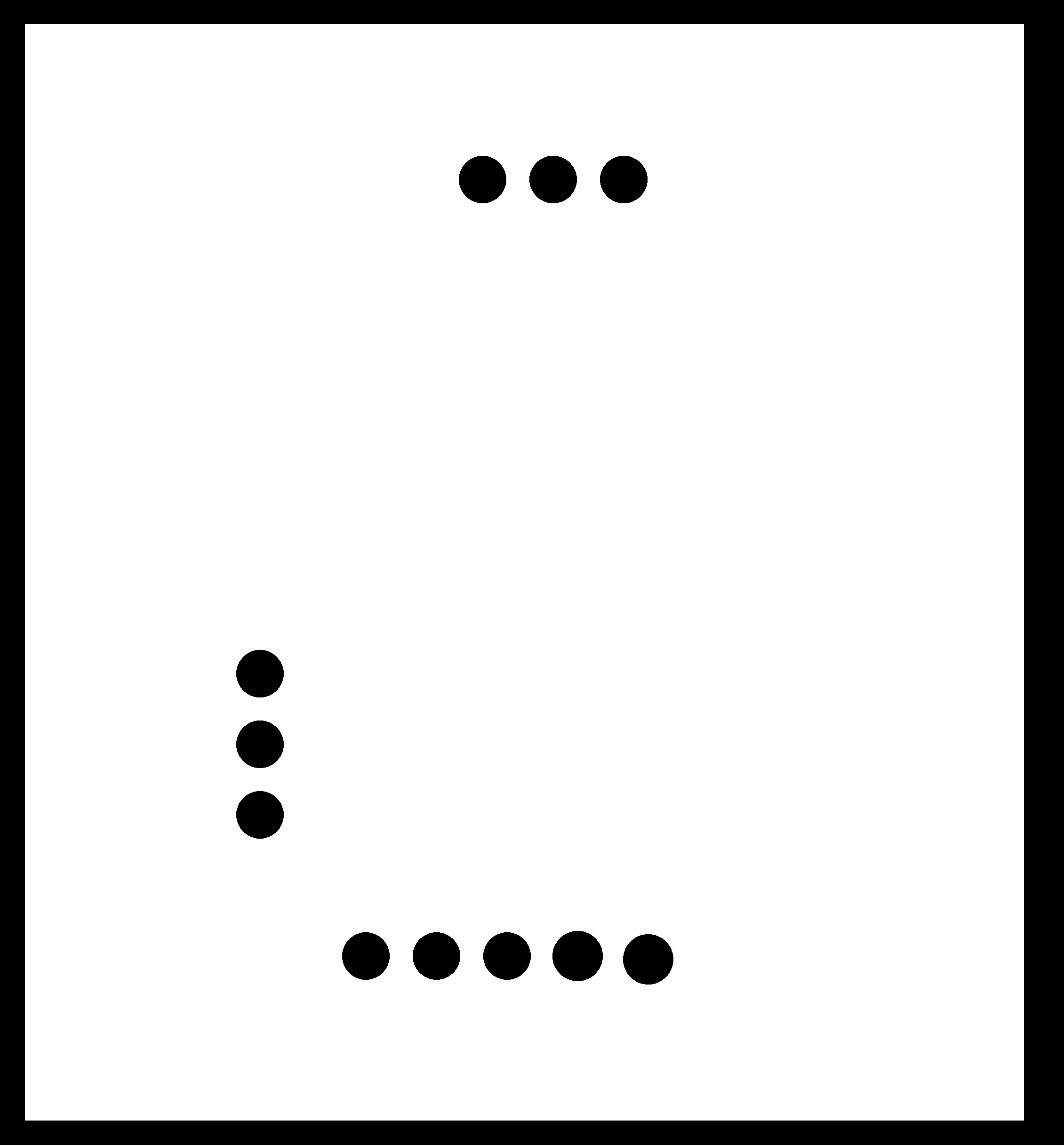
After I finished adding all the circuit components I moved on to the panel design stage, the result is as shown below

After completing the board design, I imported the design images to Adjust settings on Fab Modules
Settings Fab modules
OutLine Settings


Now that the board is ready, we start doing the experiment
The first experiment
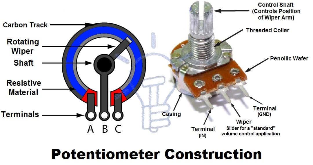
In my first experience, I used a rheostat with three LEDs and a variable resistor with my board
After they arrived with us as shown below, the LEDs were turned on one by one by controlling it with a variable resistor
- LED1 with pin 5
- LED2 with pin 6
- LED3 with pin 7
Variable resistance
- Wiper with A5
- Tirminal with VCC
- Tirminal with GND
Then I started writing the code using the Arduino software
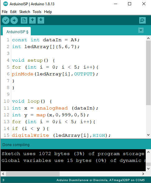
You can copy it from here
const int dataIn = A5;

int ledArray[]{5,6,7};


void setup() {

 for (int i = 0; i < 5; i++){

    pinMode(ledArray[i],OUTPUT);

  }

}


void loop() {

 int x = analogRead (dataIn);

 int y = map(x,0,999,0,5);

 for (int i = 0;i < 5; i++){

  if (i < y ){

       digitalWrite (ledArray[i],HIGH);

  }

  else {

    digitalWrite (ledArray[i],LOW);

  }

 }

 }
After we got back to the lab I was able to re-experiment with the final project board
The second experiment using Ultrasonic Sensor
In this experiment, you create a motion sensor that illuminates an LED using an ultrasound sensor
How Does an Ultrasonic Sensor Work?
Ultrasonic sensors work by emitting sound waves at a frequency too high for humans to hear. They then wait for the sound to be reflected back, calculating distance based on the time required. This is similar to how radar measures the time it takes a radio wave to return after hitting an object.
On the other hand, if an object is made out of a material that absorbs sound or is shaped in such a way that it reflects the sound waves away from the receiver, readings will be unreliable.
If you need to measure the specific distance from your sensor, this can be calculated based on this formula:
Distance = ½ T x C
(T = Time and C = the speed of sound)
At 20°C (68°F), the speed of sound is 343 meters/second (1125 feet/second), but this varies depending on temperature and humidity.

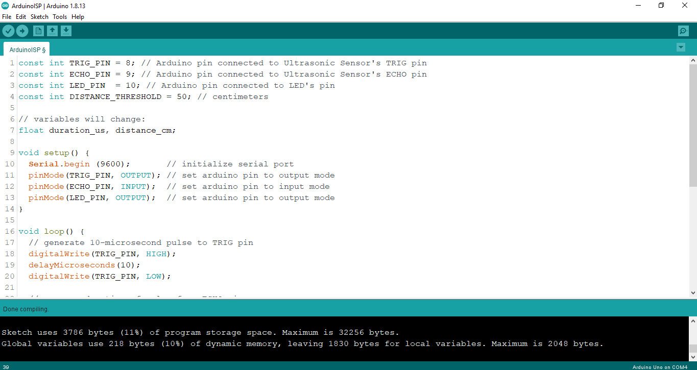
In this experiment, I used a ultrasonic sensor with an LED with my board.
senses the movement, so something moved in front of the sensor, the LED lit up.
The connections were like this
- Vcc with 5V
- GND with GND
- Trig with pin 8
- Echo with pin 9
- LED with pin 10
I wrote the code for the experiment
And this was the result
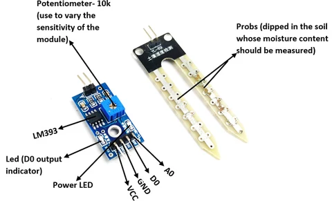
And I did an experiment with the humidity sensor that I used on the final project
int motor =6;
int sensor_pin =13;


void setup() {
  pinMode(motor, OUTPUT);
  pinMode(sensor_pin, INPUT);
}


void loop() {

  if(digitalRead(13) == HIGH)
  {
    digitalWrite(6, HIGH);
  }


  else
  {
    digitalWrite(motor, LOW);
  }


}
Conclusion
This week was awesome for me. All new and full of experiences. I am used to Arduino and everything related to it.
for download all codes check here
for download schematicsfor my board check here